Airflow Visualisation: Standards, Regulations & common Misunderstandings – ISCC 22
Summary of Morgan Polen’s Paper: Airflow Visualisation: Standards, Regulations & common Misunderstandings ISCC 22
![]() The International Confederation of Contamination Control Societies (ICCCS) is a global nonprofit organisation dedicated to advancing cleanroom technology and contamination control knowledge through international cooperation, standardisation, education and professional networking. Founded in 1972, ICCCS brings together national contamination control societies from around the world to share best practices, promote cleanroom standards and organise symposia and training events that attract contamination control specialists from multiple industries.
The International Confederation of Contamination Control Societies (ICCCS) is a global nonprofit organisation dedicated to advancing cleanroom technology and contamination control knowledge through international cooperation, standardisation, education and professional networking. Founded in 1972, ICCCS brings together national contamination control societies from around the world to share best practices, promote cleanroom standards and organise symposia and training events that attract contamination control specialists from multiple industries.
The International Symposium on Contamination Control (ISCC), organised under the ICCCS umbrella, is a biennial event that convenes industry experts and practitioners to present the latest scientific developments, practical techniques and regulatory insights in contamination control. The 25th edition of the symposium took place in 2022 held in Antalya Turkey.
One of the technical papers of particular relevance to Concept’s work in airflow visualisation at ISCC’22 was “Airflow Visualization: Standards, Regulations and Common Misunderstandings,” presented by Morgan Polen of Microrite, Inc. In this paper, Morgan draws on his professional experience in cleanroom contamination control to examine airflow visualisation as a practical contamination control tool, with specific focus on tracer particle behaviour, study methodology, and common errors observed in regulated environments. His work combines field experience and training in airflow visualisation (“smoke studies”) and particle monitoring, alongside ongoing involvement in industry standards and education.
The paper examined airflow visualisation (AVS) as a contamination control tool, rather than simply a regulatory requirement, and set out how tracer particle studies are used to evaluate the physical (actual) behaviour of HEPA and ULPA filtered air in cleanrooms, RABS, isolators and other clean air devices.
The paper examined airflow visualisation (AVS) as a contamination control tool, rather than simply a regulatory requirement, and set out how tracer particle studies are used to evaluate the physical (actual) behaviour of HEPA and ULPA filtered air in cleanrooms, RABS, isolators and other clean air devices.
Airflow visualisation studies were described as a way to:
- Characterise the contamination control effect of airflow.
- Compare real airflow patterns against design intent and operational requirements.
- Identify adverse phenomena such as dead spaces, vortices (eddy currents), refluxing air, and unintended air exchanges.
- Support risk assessment, environmental monitoring strategy, operator training, and troubleshooting of contamination issues.
An important recurring theme is that airflow visualisation should be conducted under all relevant operating conditions, including simulations of real manufacturing activities.
Cleanroom standards and regulations
The paper referenced multiple international standards and guidance documents, including:
- ISO 14644-3:2019, which describes airflow direction test and visualisation using the tracer particle injection method.
- FDA aseptic processing guidance (2004), which states that in situ air pattern analysis should demonstrate unidirectional airflow and sweeping action under dynamic conditions.
- EU GMP Annex 1 (2022), which expands expectations for airflow visualisation in cleanrooms, RABS and isolators, including testing at rest and in operation, demonstration of absence of ingress from lower grade areas, and retention of video records.
- USP <797> and USP <1116>, which distinguish between dynamic smoke pattern testing for unidirectional zones and visual smoke studies for non-unidirectional areas.
- CETA CAG-014, which provides guidance on tracer particle behaviour and cautions around heavier than air fog sources.
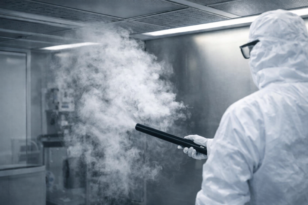
Tracer particle method and particle behaviour
A central technical theme in Morgan Polen’s paper is the Tracer Particle Method, introducing a number of fine, visible particles into the airflow so that otherwise invisible air patterns can be observed and recorded. The paper makes the point that study quality depends primarily on how faithfully the tracer particles follow the airflow, rather than how dramatic or dense the visible cloud looks. The key tracer characteristics highlighted include:
- Neutral buoyancy: the tracer cloud should not rapidly rise or settle when released into still air, so it remains driven by air currents rather than gravity.
- Stability and persistence: the tracer should remain visible long enough to allow observation of mixing behaviour and adverse patterns such as reflux, eddy currents / vortices, dead spaces, or delayed re-entrainment.
- Suitable particle size: particles must be small enough that gravity and other physical effects do not dominate their motion, while still being readily visible on video for documentation and review.
Beyond particle properties, the paper highlighted that how tracer particles are introduced is critical to study accuracy. Tracer injection should not disturb or overpower the airflow being assessed. Specific attention was given to:
- Injection location within the critical area.
- Avoiding high velocity ejection (“jetting”) that can locally dominate airflow.
- Use of ducting, stands and manifolds to introduce tracer without additional disturbance.
- Orientation of tracer manifolds, noting that slotted or single row orifice designs must be carefully positioned to avoid giving a false impression of unidirectional airflow.
Static and dynamic airflow visualisation, and common pitfalls
The paper presents airflow visualisation as needing to cover both static (at rest) studies used to document baseline airflow patterns and dynamic (in operation) studies, where real activities are simulated (equipment operation, automated motion, and personnel interventions). A key point is that many contamination control risks only become apparent under dynamic conditions, so studies limited to static testing can miss adverse airflow behaviours that matter in practice. The paper also outlines frequent shortcomings that reduce the value of AVS, including incomplete simulation of operations and interventions, inadequate video capture (camera placement / obstruction), unsuitable tracer density, injection methods that influence local airflow, tracer media that do not faithfully follow air patterns, and failure to recognise or document behaviours such as dead zones, vortices / eddy currents, refluxing air, or upward movement of air. The paper notes that poor AVS practice has been associated with / can contribute to potential compliance and quality problems, including failed media fills and regulatory observations or enforcement activity.
Relevance to airflow visualisation equipment from Concept Smoke Systems
The technical principles described in the paper, neutral buoyancy, tracer stability, controlled introduction, and suitability for both static and dynamic studies, align closely with the intended use of Concept Smoke Systems’ airflow visualisation equipment.
- Air Trace S is suited to localised airflow checks and visual confirmation of air movement in specific areas where a faster dispersing tracer is appropriate.
- B1-S supports small to medium area airflow visualisation, providing sufficient persistence to observe sweeping action, reflux or the effect of routine interventions during in operation studies.
- Mini Colt 4S is designed for larger volumes and longer observation periods, enabling the study of slower airflow behaviours such as delayed re-entrainment, dead zones and overall room circulation patterns.
A link to the article can be found on Microrite’s webite here.
This is an independent technical summary. All rights in the original presentation remain with the author/publisher.
Recommended equipment: