Airflow Visualisation in Cleanrooms – Presentation Cleanroom Technology Conference, Morgan Polen, Microrite Inc

Annex 1 and Airflow Visualisation in Cleanrooms, RABS and Isolators: Technical Summary from Morgan Polen’s Presentation
![]() The Cleanroom Technology Conference 2024 (CTC UK) is a two day UK conference and exhibition focused on cleanroom and contamination control practice, bringing together speakers and suppliers to cover regulations and standards alongside the practical realities of cleanroom design, build, validation and operation.
The Cleanroom Technology Conference 2024 (CTC UK) is a two day UK conference and exhibition focused on cleanroom and contamination control practice, bringing together speakers and suppliers to cover regulations and standards alongside the practical realities of cleanroom design, build, validation and operation.
The 2024 event took place on 22–23 May 2024 at the National Conference Centre (NCC), Birmingham, combining a technical programme with an exhibition of specialist vendors and industry experts. Concept Smoke Systems was pleased to support the event again in 2024.
One of the sessions particularly relevant to Concept’s work in airflow visualisation was “Annex 1 and Airflow Visualization concerns in Cleanrooms, RABS and Isolators”, presented by Morgan Polen of Microrite, Inc.
Morgan Polen is a cleanroom contamination control specialist with Microrite Inc whose professional work includes training and field experience focused on airflow visualisation (“smoke studies”) and particle monitoring in controlled environments. He has also contributed to industry standards and education, including participation in the U.S. Technical Advisory Group for ISO/TC 209 (ISO 14644 cleanroom standards) and involvement with professional bodies such as IEST, where he delivers training related to airflow visualisation methods and technology.
From the presentation, Annex 1 related airflow visualisation is framed around demonstrating that airflow patterns support contamination control, including evidence that:
- Air does not flow from lower grade to higher grade areas in a way that could increase risk
- Air does not travel from less clean locations (e.g. floor level) or across people / equipment in a way that could transfer contamination to critical areas
- Studies are performed “at rest” and “in operation” (including simulated interventions)
- Video recordings are retained as part of the evidence set and can inform the environmental monitoring programme
The presentation also links airflow visualisation to broader qualification / assessment activity alongside filter integrity, airflow velocity / volume, pressure differentials, recovery, and microbiological monitoring (where applicable).
Key airflow terms referenced:
The presentation included definitions and concepts commonly used in Annex 1 discussions:
- First air: filtered air that has not been interrupted before contacting exposed product or product contact surfaces.
- Unidirectional airflow: airflow moving in a single direction, intended to be uniform and sufficiently robust to sweep particles away from the critical zone.
- Turbulent airflow: airflow that is not unidirectional; air cleanliness is maintained through mixed flow dilution rather than a uniform sweep.
Static vs Dynamic Studies and Operational Simulation
In Morgan Polen’s presentation, airflow visualisation was described in two broad modes:
Static testing – Visualisation performed with conditions held as steady as possible (i.e., airflow under fixed conditions). This mode is used to document baseline airflow patterns and how air moves through the space or device when there are no deliberate disturbances.
Dynamic testing – Visualisation performed while introducing movement and operational activity, to show the effects of real operations on airflow patterns. The presentation explicitly includes both equipment motion (including automated / robotic movement) and personnel activity as part of this dynamic assessment.
A key theme in the presentation is that airflow visualisation is treated as a process simulation, meaning the study is intended to represent how the area is actually used, not only how it performs under idealised “still” conditions.
The presentation lists typical activities that may be simulated during airflow visualisation, including:
- Normal (inherent) interventions – routine actions that occur during operation
- Corrective interventions – examples cited include clearing jams, cleaning gloves, and dealing with spills/broken items
- Equipment setup and assembly – activities performed during preparation / start-up
- Equipment operating “with smoke” observing airflow while equipment is running and the tracer is introduced
- Scenarios with doors open during set-up, highlighted as an area of special emphasis (i.e., visualising airflow behaviour when doors are opened as part of set-up activities)
This static / dynamic framing connects to the Annex 1 concept (also referenced in the presentation) that airflow patterns should be evaluated both “at rest” and “in operation”, including during interventions.
Common Technical Issues Highlighted in Airflow Visualisation
1) “Jetting” and Directional Bias from the Smoke Source
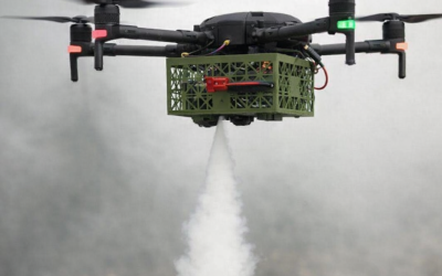
A recurring technical concern described in the presentation is jetting, where the tracer source produces a noticeable directional “push” (for example, from a manifold with outlets concentrated on one side). If the momentum is high enough, it can locally overpower the real airflow and distort what the visualisation appears to show.
With that said, when used deliberately and gently, a controlled directional release can also be a practical technique helping to seed the tracer particles consistently into the airstream or form a thin “curtain” across an opening (doors, pass-throughs, transfer points) to make boundary crossing and ingress / egress behaviour easier to observe on camera.
The key distinction is whether the directionality is low-momentum and documented as an introduction method, versus strong enough to become the dominant flow in the area being assessed.
2) Heavier-than-Air Fog Sources (and “Pure Water” Requirements)
The presentation contrasted tracer behaviours and highlighted potential limitations of some heavier than air fog approaches. In the examples discussed, a fog that tends to settle or disperses very quickly can make interpretation more challenging, particularly when the study objective is to observe stagnant regions, slow clearing, or delayed re-entrainment.
The presentation also referenced guidance stating that the visible medium should be as close to neutrally buoyant as possible, noting that heavier than air fog may not accurately represent actual air patterns and can diffuse rapidly.
In practice many regulated cleanroom users specify constraints on the visualisation medium itself, most commonly a requirement for water only (“pure water”) systems with no active ingredient (e.g. glycols, oils) added tracer chemistry. This is driven by internal contamination control policies, product contact risk assessments, or cleaning / housekeeping considerations.
For this water only specification, Concept can support airflow visualisation and operational demonstrations pure water foggers such as the AFM-NEO range, whilst also offering sub-micron tracer systems (e.g., B1-S, Mini Colt 4S, Air Trace S) where the study objective calls for longer persistence and tracer behaviour closer to neutral buoyancy.
This article summarises the key technical themes from Morgan Polen’s presentation on airflow visualisation (“smoke studies”) for cleanrooms, RABS and isolators, particularly the emphasis on using smoke (often described technically as tracer particles) that is as close to neutrally buoyant as practical, and introducing it in a controlled way so the visible cloud follows true airflow patterns rather than being dominated by the release method.
It also highlights why study design commonly includes both static observations (baseline airflow under fixed conditions) and dynamic observations (equipment movement, operator interventions, doors opening during set-up), because real operations can change air currents and expose behaviours such as turbulence, eddies, reflux and dead zones that may not be obvious from point measurements alone.
Concept Smoke Systems equipment is designed to support these airflow visualisation tasks across different cleanroom scenarios by matching the persistence and deployment method to the objective:
- Air Trace S is suited to localised, short-duration checks where a fast-dispersing tracer is preferred, for example visualising airflow direction at a specific interface, transfer point or workstation without filling the entire space. Its battery operation supports practical use during in operation simulations where mains cabling would be intrusive.
- B1-S is aimed at small to medium area airflow visualisation where a more sustained plume is helpful for filming and interpreting patterns such as sweeping action, minor refluxing, or the effect of routine interventions. Being battery powered, it is well matched to “in operation” studies where repeatable placement and mobility matter.
- Mini Colt 4S is intended for larger volumes and longer observation windows, where a highly persistent effect supports studying slower behaviours such as delayed clearing, re-entrainment and broad room circulation patterns. It preheats on mains power and retains the heat for a limited period allowing it to be used off power once ready, useful when you want the visualisation without cables influencing operator movement or the filming setup. It also means the “recharge” time is a maximum of 5 minutes.
Taken together, these three systems provide a practical toolkit for airflow visualisation, from quick, targeted checks through to medium scale operational studies and large area mapping, supporting the core objective described in the presentation: making airflow patterns visible so they can be recorded, interpreted and documented in a way that reflects real cleanroom use.
Clarification:
In Morgan’s presentation, the term “tracer particle” is essentially the technical way of describing what many people would call artificial smoke or fog used for airflow visualisation. “Smoke / fog” is convenient plain English, but “tracer aerosol / particle” is often the more precise description because the goal isn’t theatrical effect, it’s to introduce very fine, visible particles that behave like the air stream so the airflow can be observed and recorded.
In this context, the “smoke” is a cloud of sub-micron liquid aerosol particles designed to remain suspended and be as close to neutrally buoyant as practical, so the visible plume follows airflow patterns rather than sinking or rising due to its own weight.
This is an independent technical summary of a publicly available presentation. Concept Smoke Systems is not affiliated with Microrite, and all trademarks belong to their respective owners.
Recommended equipment: